Description
Port & Physical Interface Configuration
-
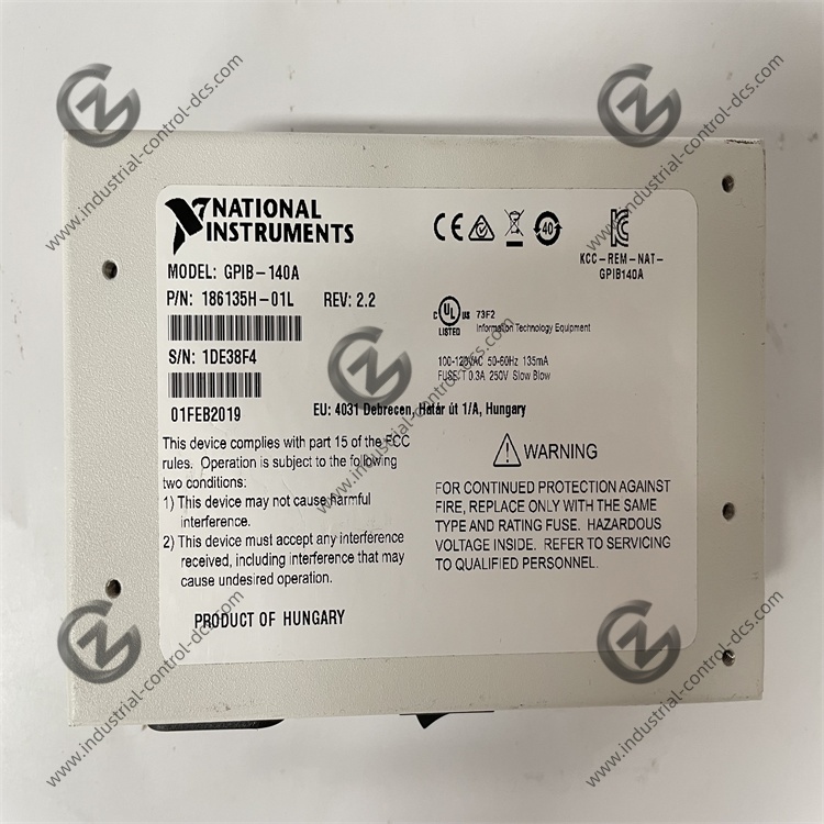
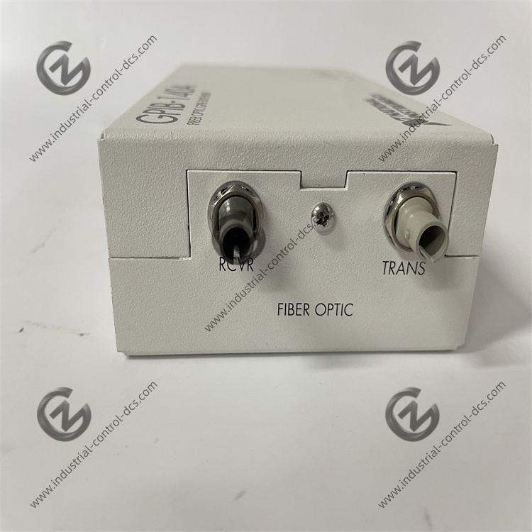
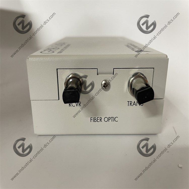
Dual Standard Interfaces: 1×IEEE 488 GPIB port (24-pin standard connector), 1×ST-type duplex fiber transceiver port; matched HFBR1414/HFBR2416 optical chips for multi-mode transmission
-
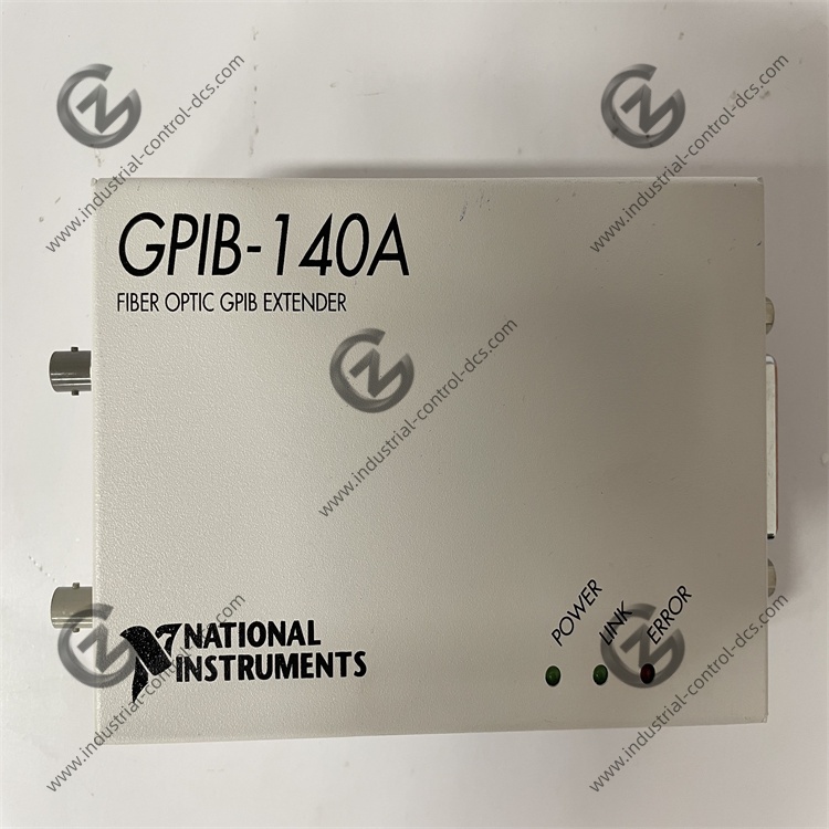
Status Indicators: 3 front-panel LEDs: PWR (power status), LINK (fiber synchronization), ACT (GPIB bus read/write activity)
-
Mechanical Mounting: Standard 35mm DIN rail snap mounting, optional panel screw mounting; no chassis ventilation gap required for static heat dissipation
-
Physical Dimensions: 124 × 72 × 45 mm, bare weight 220 g, flame-retardant ABS housing, IP30 front panel dust protection
-
Power Input: Universal 100–240 VAC 50/60Hz built-in isolated power supply, no external DC adapter required
Core GPIB & Optical Transmission Parameters
-
Protocol Compatibility: Full compliance with IEEE 488.1, IEEE 488.2 and HS488 high-speed handshake protocols, transparent to upper-layer GPIB controller software
-
Data Throughput: 1.1 MB/s max for IEEE 488.1 unbuffered mode; 2.8 MB/s max for HS488 high-speed handshake mode
-
Transmission Distance: GPIB-140A: 1 km multi-mode 62.5/125μm fiber; GPIB-140A/2: 2 km single-mode 9/125μm fiber, non-interchangeable transceivers
-
Bus Device Loading: Original GPIB limit 15 devices; extended bus total capacity 28 devices including two paired extenders
-
Link Latency: 3.2 μs fixed round-trip fiber link delay, no impact on standard instrument timeout settings
DIP Switch Configuration & Operation Modes
-
Buffered/Unbuffered Mode: DIP1 OFF = unbuffered (low latency for short fiber links); DIP1 ON = buffered (anti-data loss for long-distance fiber attenuation)
-
Parallel Poll Response (PPR): DIP2 OFF = Immediate PPR (real-time poll response); DIP2 ON = Latched PPR (fault state retention for intermittent bus faults)
-
HS488 Handshake Toggle: DIP3 reserved for HS488 enable/disable; auto-fallback to standard 3-wire handshake for non-HS488 instruments
-
Pair Matching Rule: Paired transmit/receive extenders must use identical DIP settings, mismatched configuration causes permanent link failure
Isolation & EMC Anti-Interference Performance
-
Galvanic Isolation: Complete electrical isolation between local and remote GPIB bus via optical fiber, zero ground loop current between different earth potential cabinets
-
Dielectric Withstand: 2,500 Vrms 1-minute isolation withstand between GPIB port and internal power circuit, meeting CAT II lab safety standards
-
EMC Immunity: Compliant with EN 61326-1 industrial test equipment standard, resistant to high-frequency EMI from variable frequency drives and power relays
-
Lightning Surge Protection: Built-in TVS surge suppression on GPIB signal lines, withstands ±2kV common-mode lightning surge
Environmental & Reliability Specifications
-
Operating Temperature: 0 ℃ ~ 50 ℃ continuous operation; storage temperature -20 ℃ ~ 70 ℃
-
Humidity Rating: 10%–90% RH non-condensing for operation and storage
-
Vibration Resistance: 2 grms 10–150 Hz random vibration, qualified for indoor test cabinet fixed installation
-
MTBF Index: 280,000 hours mean time between failures under standard lab ambient conditions
-
Altitude Derating: Full performance within 2000m; optical link power attenuation requires fiber margin adjustment above 2000m
Compatibility Matching List
-
Matching GPIB Controllers: NI GPIB-USB-HS, PCI-GPIB, PXI-GPIB all generations
-
Peer NI Extender Comparison: GPIB-120B (copper 20m extension, no isolation); GPIB-140A (fiber long-distance isolation)
-
Official Replacement Model: NI GPIB-142A upgraded fiber extender with auto link calibration and wider temperature range
-
Official Status: Fully end-of-life since 2018, no firmware updates, only calibrated aftermarket inventory and third-party repair
Software Compatibility
-
Required Drivers: NI-488.2 driver V15.5 and earlier, NI-VISA full version
-
Configuration Tools: NI MAX, GPIB Analyzer bus debugging utility
-
Development Software: LabVIEW all versions, LabWindows/CVI, C#, Python PyVISA
-
Supported OS: Windows XP/7/10; limited Windows 11 compatibility with legacy driver patch, no Linux official driver
Pros & Limitations
-
Pros: Fiber-based full galvanic isolation eliminating ground loop faults, transparent GPIB protocol with no instrument code modification, dual transmission modes adapting variable fiber quality, DIN rail compact installation, wide legacy software compatibility, high surge immunity for harsh test environments
-
Limitations: Requires paired deployment, cannot work standalone, fixed ST fiber interface incompatible with SC connectors, narrow 0-50℃ operating temperature, obsolete driver support, no remote link fault diagnosis
Official Product Images & Visual Reference
-
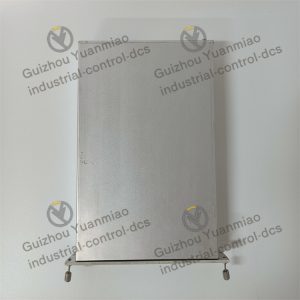
Front Panel Render: Grey DIN rail housing, three centralized status LEDs, side DIP switch access panel
-
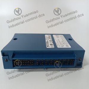
Port Side Photo: Rear GPIB standard port and ST duplex fiber transceiver jack layout
-
Paired Assembly: Dual GPIB-140A cross-room fiber interconnection typical wiring diagram
-
Document Source: NI official user manual 373124B-01, unwatermarked factory hardware drawings
Reviews
There are no reviews yet.