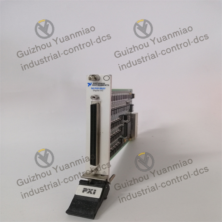
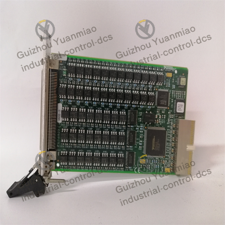
Description
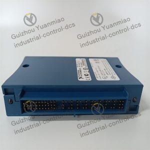
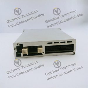
NI PXI-6527 48-bit parallel isolated digital I/O interface module
Hardware connection and configuration factors
Power supply stability
The module relies on a + 5VDC power supply (with a maximum power of 500mA). If the supply voltage fluctuates by more than ±5% (such as lower than 4.75V or higher than 5.25V), it may cause abnormal judgment of digital logic levels (such as misidentifying high and low levels in the input channel), and a decrease in output driving capability (switching current less than 120mA).
Excessive power supply ripple (such as exceeding 50mV) will introduce noise, interfere with the isolation circuit, and cause false triggering of the input channel or jitter of the output signal.
Wiring and connector losses
If the 100-pin connector has poor contact (such as oxidation or loosening), it will cause input signal attenuation (for example, a 24V input drops below 20V, which may be identified as logic low) or output open circuit, affecting the reliability of the I/O channel.
If the cable is too long (such as over 10 meters) or the impedance does not match, it will cause signal transmission delay (the rising/falling edges become slower), and even reflect noise, especially when high-frequency digital signals (such as > 100 KHZ) are transmitted.
Load matching
When the output channel drives the load, if the load current exceeds 120mA (such as when the power of the external relay coil is too large), it may cause the solid-state relay to overheat. Long-term use will reduce its lifespan or even burn it out. If the load is capacitive (such as a large capacitor), the instantaneous inrush current of the switch may exceed the rated value, causing the protection circuit to act.
If the input channel is not connected with a matching resistor (such as in a suspended state), it is prone to electromagnetic interference and error codes (logic level jumps) may occur.
Environment and interfering factors
Electromagnetic Interference (EMI) and radio frequency Interference (RFI)
When the module is close to a strong electromagnetic source (such as a frequency converter or motor), the optocoupler in the isolation circuit may be interfered with by electromagnetic pulses, causing misreading of the input channel (such as logic 0 jumping to logic 1) and abnormal switch state of the output channel.
High-frequency radiation (such as from wireless devices) may couple into cables, causing common-mode interference. When the isolation voltage exceeds 60VDC, it will break through the isolation barrier and affect signal integrity.
Temperature and humidity
When the operating temperature exceeds the range of 0 to 50℃, the performance of internal components of the module (such as solid-state relays and optocouplers) will decline: excessively high temperatures (such as 60℃) will lead to a decrease in isolation withstand voltage (from 60VDC to below 40VDC) and input threshold drift (the logic high level judgment point moves upward). Too low a temperature (such as -10 ℃) may cause a delay in the relay response.
When the humidity exceeds 85% RH, the connector may get damp and rust, increasing the contact resistance. At the same time, condensation water is prone to occur on the internal circuit board, causing short circuit faults.
Mechanical vibration and shock
Severe vibration (such as when installed on a moving platform) may cause the connector pins to loosen or the internal solder joints to crack, resulting in intermittent communication failures (such as random failure of the I/O channel).
Signal characteristics and parameter Settings
Input signal level and rising edge
The input signal voltage must be strictly within the range of 0 to 28VDC: a voltage lower than 0V May damage the input circuit, while a voltage higher than 28VDC will exceed the isolation withstand voltage of the optocoupler, resulting in permanent damage to the channel. If the rising/falling edge of the signal is too slow (such as > 10μs), the module may misjudge it as a level jump, resulting in false input.
Output the switching frequency and duty cycle
If the switching frequency of a solid-state relay exceeds the rated value (usually <10kHz), its lifespan will be reduced due to increased thermal loss of the contacts. Excessively high duty cycle (such as continuous conduction for more than 8 hours) may cause the relay to overheat, increase the output impedance (such as from 10Ω to 50Ω), and affect the load driving capability.
Isolation configuration and grounding
Although the input/output channels of the module have been isolated, if they are not properly grounded (such as when the chassis is not connected to a protective ground), the ground loop will introduce common-mode voltage (exceeding 60VDC), which will undermine the isolation effect and cause signal distortion.
When multiple modules are cascaded, if the grounding potential difference between each module is too large (>10V), leakage current may occur, which can interfere with the logic of digital signals.
Software and drivers
Driver compatibility
Not installing the compatible NI driver (such as not optimized for Windows 10) or having a low version may lead to incorrect configuration of the I/O channel (such as reversed input/output directions), interrupt response delay (exceeding 1ms), or even a blue screen of the system.
Data transmission and timing control
During high-speed data acquisition (such as operating 48 channels simultaneously), if the frequency of software API calls exceeds the processing capacity of the module (such as insufficient PCI bus bandwidth), it will lead to data packet loss (I/O status not updated in time).
Improper timing logic Settings (such as output pulse width < 10μs) may be ignored by the module and fail to trigger the action of external devices.
Maintenance and usage specifications
Hot plugging operation
The module does not support hot plugging. Plugging and unplugging while powered on will generate instantaneous high voltage (up to over 100V), which can break down the isolation circuit and cause permanent failure of the input/output channels.
Overload and misoperation
Mistakenly connecting an AC signal (such as 220V AC) to a DC input channel or short-circuiting the output terminal will directly burn out the internal solid-state relay and optocoupler components.
Operating at full load (120mA) for a long time without reserving a margin of more than 20% will accelerate the aging of components and reduce the module’s lifespan (such as shortening the expected lifespan from 5 years to 2 years).
Reviews
There are no reviews yet.