ABB REG216 System
ABB REG216 is a modular product specially designed for generator protection. Adopting advanced digital technology, it features high flexibility and reliability, and is suitable for various types of generator sets. The detailed introduction is as follows:
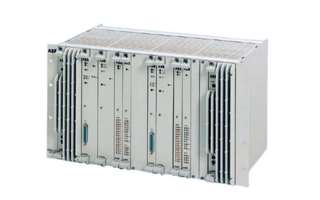
System Composition
-
Main System Interface
- It includes the 216GW62 component, which is used to adjust the signal level and isolate the primary system CT and PT circuits from the electronic circuits of the protection device. It can accommodate up to 12 transformers, and 4 components provide a total of 48 input terminals.
- The 216GD61a auxiliary relay and optocoupler component is also included, providing 8 trip relays, 16 auxiliary relays, and 16 optocouplers, with a maximum of 4 installable units.
-
Parallel Bus and Electronic Units
- The electronic units adopt a plug-in design and are installed in a 19-inch 6U equipment rack, which can be divided into 21 standard partitions. Data exchange is carried out through the parallel bus B448C, based on the IEEE P896 specification, featuring address and data time multiplexing.
- It includes various units such as the processing unit 216VC62a, analog input unit 216EA62, digital output unit 216AB61, trip output and binary input unit 216DB61, and auxiliary DC power supply device 216NG61.
Functional Features
-
Comprehensive Protection Functions
It can provide overcurrent protection, undervoltage protection, overvoltage protection, reverse power protection, etc. It also adopts differential protection technology based on the vector product principle, with a differential protection action time of less than 30ms, effectively protecting the generator. -
Real-time Monitoring and Self-checking
It has a real-time monitoring function to collect sensor data in real time. It can also execute cyclic test routines through software to continuously self-monitor the hardware and promptly detect potential faults. -
Modular Design
Both hardware and software adopt a modular design, allowing users to add or remove functional modules according to actual needs to adapt to different scales and application scenarios. -
Distributed Control and Communication Capability
It is commonly used in Distributed Control Systems (DCS) to remotely monitor and control multiple devices and processes. Equipped with communication interfaces, it can exchange data and communicate with other automation devices, PLCs, SCADA systems, etc. -
Programmability
It can be configured and programmed according to the needs of specific applications to meet the requirements of different industrial processes.
Application Fields
It is widely used in power plants, renewable energy facilities, and other industrial applications to protect generators, ensuring the reliability and stability of the entire system.
The installation of ABB REG216 system can be divided into steps such as hardware installation and software configuration. The specific introduction is as follows:
Pre-installation Preparations
-
Confirm completeness of equipment and accessories
Check whether all components of the REG216 system are intact, including main system interface components, electronic units, various relay modules, power modules, etc., and ensure that accessories such as prefabricated shielded cables and installation screws are not missing. -
Plan the installation location
Select a suitable installation location according to the system scale and actual needs, generally installable in a standard 19-inch rack or electrical compartment. Ensure that the installation location has good ventilation and heat dissipation conditions, is far away from strong electromagnetic interference sources, and is convenient for wiring and maintenance. -
Prepare tools
Prepare installation tools such as screwdrivers and wrenches, as well as testing tools such as multimeters.
Hardware Installation
-
Install the rack or compartment
If rack installation is adopted, fix the 19-inch rack in the appropriate position; if an electrical compartment is used, ensure that the compartment is firmly installed and well grounded. -
Install main system interface components
Install main system interface devices such as input transformer components into the corresponding positions in the rack or compartment (e.g., 216GW62 component), and fix them with screws to ensure firm installation. -
Install electronic units
Insert electronic units such as the processing unit 216VC62a and analog input unit 216EA62 into the standard slots of the rack, paying attention to inserting them tightly to ensure good contact. -
Install relay modules and other components
According to needs, install components such as the 216GD61a auxiliary relay and optocoupler component, trip output and binary input unit 216DB61 into the rack or compartment, complete the fixation, and connect the internal cables. -
Connect cables
Use standard prefabricated shielded cables to connect the main system interface with electronic units and the connection lines between modules, ensuring correct and firm cable connections, and paying attention to the grounding of the shield layer. Meanwhile, connect the cables from current transformers (CT) and voltage transformers (PT) to the main system interface, noting the correct wiring polarity. -
Connect power supply
Access power modules such as the auxiliary DC power supply device 216NG61 to the system, connect the AC or DC power input lines, ensure correct power polarity, and check whether the power voltage meets the system requirements.
Software Configuration
-
Access configuration equipment
Connect to the REG216 system through the serial interface of a PC, and use special configuration software for parameter setting. -
Set system parameters
Set relevant parameters such as CT/PT transformation ratios, protection function thresholds, action times, etc., according to the rated parameters and operating requirements of the generator and transformer. -
Configure protection functions
Select required protection functions (such as overcurrent protection, overvoltage protection, etc.) from the protection function library, activate them, and perform corresponding parameter settings to determine the logical relationship and action output of each protection function. -
Define input and output signals
Define binary input and output signals, determine which signals are used for tripping, which for alarming, etc., as well as the associated objects and action logic of the signals.
Debugging and Testing
-
Pre-power-on inspection
Recheck whether all hardware connections are correct, whether screws are tightened, whether cables are damaged, etc., to ensure no short circuits, open circuits, or other conditions. -
Power-on testing
Switch on the power, observe whether the indicator lights of each system module are normally on, check whether the system can start normally, and whether there are error messages. -
Function testing
Use testing equipment to simulate various fault conditions (such as inputting overcurrent and overvoltage signals), check whether the protection system can correctly act according to the set logic, and output corresponding tripping or alarm signals. Meanwhile, check whether the measurement function is accurate and whether the measured values match the actual values. -
Communication testing
If the REG216 system needs to communicate with other control systems, perform communication testing to ensure normal data transmission and accurate information interaction with other systems.