
Description
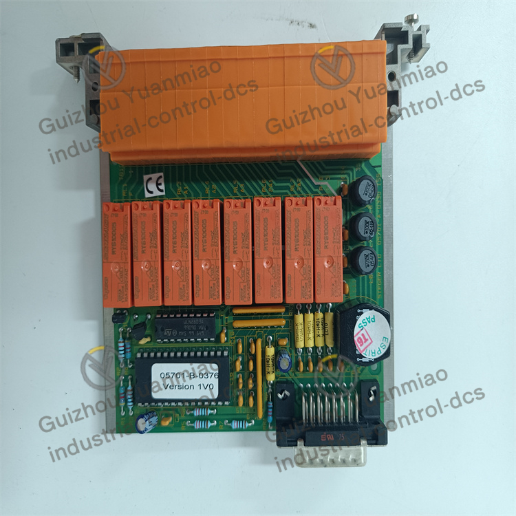
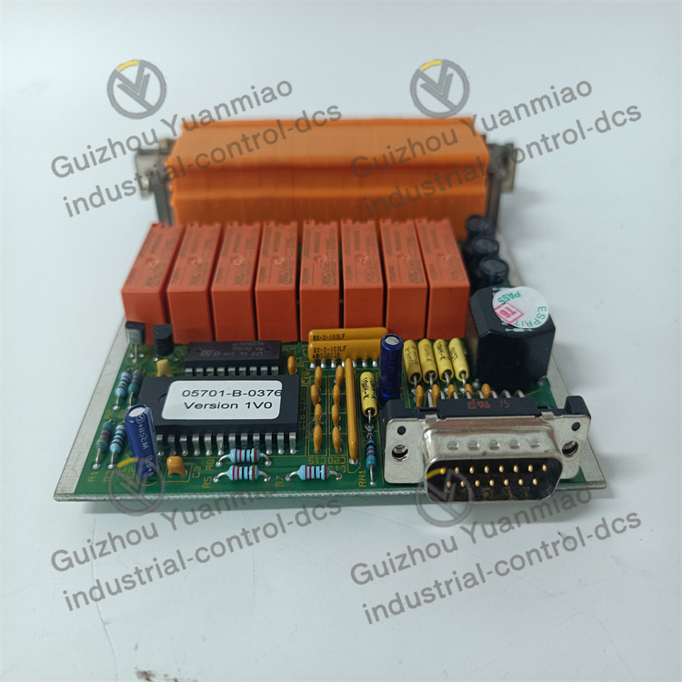
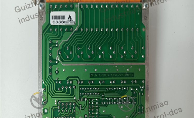
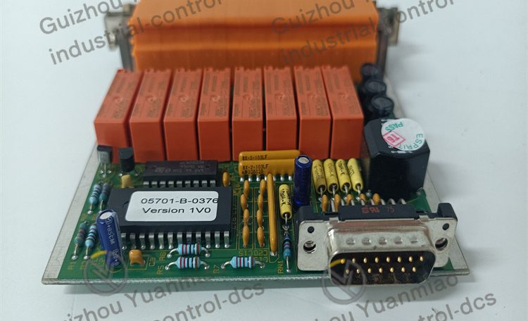
Honeywell 05701-A-0330 Control Card
I. Hardware Architecture and Core Components
As a key component of industrial automation systems, the working principle of this control card is based on the closed-loop logic of “signal acquisition-processing-output control”. The core hardware includes:
- Central Processing Unit (CPU): Responsible for executing control algorithms, logical operations, and data processing, coordinating the work of each module.
- Input/Output (I/O) Interfaces:
- Analog input channels: Receive 4-20mA or voltage signals from sensors (such as temperature and pressure transmitters).
- Digital input/output channels: Process switch signals (such as button and relay status) and control actuator actions.
- Communication Module: Supports protocols such as Modbus RTU and RS-485 to communicate with upper computers (PLC, DCS) or other devices.
- Power Management Unit: Converts 24VDC power into stable voltages required by each component to ensure power supply reliability.
- Storage Unit: Stores control programs, configuration parameters, and fault logs, supporting power-off data retention.
II. Signal Processing and Control Logic Flow
1. Signal Acquisition Stage
- Analog acquisition: Convert continuous electrical signals (such as 4-20mA current) input by sensors into digital quantities through a 16-bit ADC (Analog-to-Digital Converter), with a resolution of ±0.05% FSR to ensure high-precision sampling.
- Digital acquisition: Read switch signals (ON/OFF), such as valve status and equipment start/stop signals, and convert them into binary data.
2. Data Processing and Algorithm Execution
- Preprocessing: Filter the collected data (eliminate electromagnetic interference) and perform linearization correction (compensate for sensor nonlinear errors).
- Control algorithm operation: Process the data according to preset logic (such as PID control, sequential control) to generate control instructions. For example:
- In temperature control scenarios, the CPU compares the set value with the measured temperature and calculates the PID parameter output adjustment.
- In logic control scenarios, judge whether to trigger output actions according to the combination of input signals (such as safety interlock conditions).
3. Control Output Stage
- Analog output: Convert digital control instructions into 4-20mA current or 0-10V voltage signals through a 16-bit DAC (Digital-to-Analog Converter) to drive actuators such as control valves and frequency converters.
- Digital output: Output switch signals through relays or transistors to control motor start/stop, valve switch, etc.
4. Communication and System Interaction
- Communicate with upper computers or other modules through the RS-485 interface, upload real-time data (such as acquisition values and device status), and receive remote instructions (such as parameter modification and manual control).
- Support the Modbus RTU protocol to ensure compatibility with devices from different brands and achieve system integration.
III. Principles of Key Function Implementation
Redundancy and Self-Diagnosis Mechanism
- Built-in watchdog timer: Monitor the CPU operation status in real time. If the program is abnormal, it will automatically reset to prevent crashes.
- Hardware status monitoring: Continuously detect faults in power supply, I/O channels, communication links, etc., and alarm through indicator lights or communication interfaces.
Anti-Interference and Isolation Design
- Electrical isolation between channels (1000VDC): Avoid mutual interference between signal channels and prevent external high voltage from damaging internal circuits.
- EMC compatible design: Complies with IEC 61000-4 standards, reducing the impact of electromagnetic interference through filtering, shielding, and other measures.
Flexible Configuration Principle
- Through software tools (such as Honeywell’s dedicated configuration software), you can customize I/O channel types (voltage/current), range, filtering parameters, etc., to adapt to different sensors and actuators.
IV. Workflow in Typical Application Scenarios
Take “temperature closed-loop control” as an example:
- Signal acquisition: The resistance signal output by the thermistor sensor → the analog input channel of the control card converts it into a voltage signal → the ADC converts it into a digital quantity.
- Processing and calculation: The CPU compares the measured temperature with the set value and calculates the PID adjustment (such as P=20%, I=5s, D=10%).
- Output control: The DAC converts the digital adjustment into 4-20mA current → drives the opening of the electric control valve to adjust the flow of the heating medium.
- Feedback and optimization: Re-acquire the temperature in the next cycle and repeat the above process until the temperature stabilizes within ±0.5°C of the set value.
V. Principles of System Integration
As a distributed I/O node, the 05701-A-0330 control card integrates into industrial automation systems in the following ways:
- Data interaction: Send real-time data (such as I/O status and fault information) to the upper computer and receive control instructions (such as parameter modification).
- Collaborative control: Cooperate with PLC/DCS systems to execute complex logic control (such as multi-device interlocking and sequential start-up).
- Remote monitoring: Achieve remote configuration, status monitoring, and fault diagnosis through the SCADA system to improve system management efficiency.
Conclusion
The Honeywell 05701-A-0330 control card realizes high-precision acquisition, intelligent processing, and reliable control of industrial field signals through a design of “hardware modularization + software programmability”. Its core advantages lie in anti-interference capability, self-diagnosis function, and flexible system integration, making it suitable for process control, building automation, and other scenarios requiring high reliability.
Reviews
There are no reviews yet.