Description
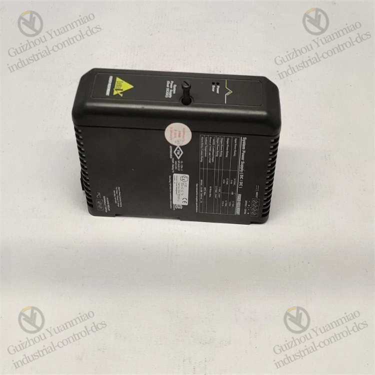
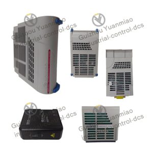
Emerson KJ1501X1-BC1 Module
As a power module in the DeltaV series, Emerson KJ1501X1-BC1 may malfunction due to load fluctuations, environmental interference, or component aging during long-term operation in industrial environments. The following are common faults and corresponding solutions, sorted out based on the module’s characteristics and general maintenance logic of industrial power supplies:
I. Abnormal Output Voltage (No Output / Low Voltage / High Voltage)
Fault Phenomena:
- No 24VDC output, and the downstream equipment is powered off;
- The output voltage is lower than 24VDC (e.g., 20-23VDC), causing unstable operation of the equipment;
- The output voltage is higher than 24VDC (e.g., 25-28VDC), which may burn out the load equipment.
Possible Causes and Solutions:
Input Power Supply Issues
- The input voltage (120/240VAC) is not connected or unstable, or the input line is loose or has poor contact.
- Solution: Use a multimeter to check if the input voltage is normal; inspect the tightness of the power input terminals and plugs, and replace damaged cables or connectors.
Output Overload or Short Circuit
- The load current of the downstream equipment exceeds the rated output current of the module (e.g., exceeding 10A), or the output line is short-circuited (e.g., cable damage, load short circuit), triggering the module’s protection mechanism.
- Solution: Disconnect all loads and test the module’s output alone to see if it returns to normal; connect the loads step by step to check for overloaded equipment or short-circuit points; restart the module after replacing the faulty load.
Aging or Damage of Internal Components
- The output rectifier diodes and filter capacitors are aged (e.g., capacitor bulging, leakage), or the PWM control chip and switching tube (MOSFET) are damaged, resulting in voltage regulation failure.
- Solution: After powering off, disassemble the module (to be operated by professionals), check the appearance of capacitors, diodes, and other components; replace damaged components (it is recommended to use original accessories); if the core circuit is damaged, the module needs to be replaced entirely.
Feedback Loop Fault
- The output voltage sampling resistor and optocoupler feedback components are faulty, causing the control circuit to fail to accurately monitor the output voltage and resulting in voltage regulation failure.
- Solution: Detect the parameters of feedback loop components (e.g., resistor resistance, optocoupler conductivity), replace abnormal components; calibrate the reference voltage of the feedback circuit.
![]()
II. Module Overheating or Automatic Shutdown
Fault Phenomena:
- The temperature of the module housing is too high (exceeding the operating upper limit of 70℃);
- It shuts down suddenly during operation, can start briefly after cooling, and the fault repeats.
Possible Causes and Solutions:
Poor Environmental Heat Dissipation
- Insufficient ventilation at the installation location, the ambient temperature exceeds 70℃, or dust accumulates on the module surface, blocking the heat dissipation holes.
- Solution: Clean the dust on the module surface and heat dissipation holes; adjust the installation position to ensure ventilation gaps (it is recommended to be ≥10cm); install heat dissipation fans or cooling devices in high-temperature environments.
Long-Term Full-Load Operation of the Load
- The output current is close to or reaches the rated value for a long time (e.g., 10A), leading to increased heat generation of components such as switching tubes and transformers.
- Solution: Check the total load current; if it exceeds the rated value of the module, it is necessary to shunt the load or replace it with a higher-power power module (e.g., parallel modules of the same model to achieve current sharing).
Fault of Internal Heat Dissipation Components
- The cooling fan (if any) is damaged, the heat sink is loose, or the thermal grease is aged, resulting in reduced heat dissipation efficiency.
- Solution: Replace the faulty fan; re-fix the heat sink and apply new thermal grease; check if the heat dissipation channel is blocked by internal components.
False Trigger of Thermal Protection Circuit
- The thermistor is faulty or the thermal protection threshold drifts, causing the module to shut down falsely at normal temperatures.
- Solution: Detect whether the resistance of the thermistor is normal (usually around 10kΩ at room temperature); calibrate or replace the components of the thermal protection circuit.
III. Input Power Tripping or Fuse Blowing
Fault Phenomena:
- After connecting to AC power, the upper-level air switch or the built-in fuse of the module trips/blows immediately.
Possible Causes and Solutions:
Input Circuit Short Circuit
- The input rectifier bridge is damaged (diode breakdown), and the EMI filter capacitor is short-circuited, resulting in an instantaneous excessive input current.
- Solution: Disconnect the input power, use a multimeter to check if the rectifier bridge and filter capacitor are short-circuited; replace damaged components and the blown fuse (the rated current must be matched, such as the specification specified by the original factory).
Internal Short Circuit of the Module
- The switching tube is broken down, and the high-frequency transformer winding is short-circuited, causing a short circuit between the primary and secondary sides.
- Solution: Detect the insulation resistance between the drain and source of the switching tube (MOSFET) and between the primary and secondary of the transformer (should be ≥10MΩ); replace faulty components; if the transformer is damaged, it is recommended to replace the module entirely.
Abnormal Input Voltage
- The input voltage far exceeds the 120/240VAC range (e.g., mistakenly connected to 380VAC), causing overvoltage damage to components.
- Solution: Confirm whether the input power voltage meets the module specifications; replace components damaged by overvoltage (e.g., varistors, rectifier bridges), and check whether the upper-level power switch is misoperated.
![]()
IV. Excessive Output Ripple Causing Interference to Load Equipment
Fault Phenomena:
- Downstream equipment (e.g., sensors, controllers) has data fluctuations and misoperations; the output voltage ripple detected by an oscilloscope exceeds the standard value (usually required to be ≤100mV peak-to-peak).
Possible Causes and Solutions:
Aging of Output Filter Capacitors
- The capacity of electrolytic capacitors is attenuated, and ESR (equivalent series resistance) increases, making it impossible to effectively filter out high-frequency ripples.
- Solution: Replace the output filter capacitor (it is necessary to match the capacity and withstand voltage, e.g., 470μF/50V is commonly used for 24VDC output).
High-Frequency Transformer Noise Coupling
- Poor grounding of the transformer shielding layer, or poor insulation between the primary/secondary windings, leading to high-frequency noise 窜入 the output end.
- Solution: Check whether the transformer shielding layer is reliably grounded; rewind the windings or replace the transformer (professional maintenance is required).
Abnormal PWM Control Signal
- The PWM waveform output by the control chip is distorted, causing unstable on/off time of the switching tube and generating additional ripples.
- Solution: Detect whether the power supply voltage of the PWM control chip is stable; replace the abnormal control chip or surrounding oscillating components (e.g., crystal oscillator, resistor).

V. Module Failure to Communicate or Abnormal Status Indicator Light (If Equipped with Communication Function)
Fault Phenomena:
- The status indicator light is not on or flickers abnormally, or the power status (e.g., voltage, current, temperature) cannot be monitored through the DeltaV system.
Possible Causes and Solutions:
Communication Interface Fault
- The communication cable is loose, the connector is oxidized, or the internal communication chip of the module (e.g., Modbus/HART chip) is damaged.
- Solution: Re-plug the communication cable and clean the connector; detect the power supply and pin signals of the communication chip, and replace the damaged chip.
Indicator Light Circuit Fault
- The indicator LED is damaged or the current-limiting resistor is burned out.
- Solution: Replace the faulty LED or resistor; if the indicator light is controlled by the main control chip, it is necessary to check whether the chip outputs the driving signal normally.
Firmware or Configuration Error
- The internal firmware program of the module is wrong, or the communication parameters (e.g., address, baud rate) do not match the system.
- Solution: Re-flash the module firmware through the DeltaV system; check and modify the communication parameters to match the system.
VI. General Maintenance Suggestions
- Regular Inspection: Inspect the module’s appearance (no bulging, leakage, or burning marks), the tightness of input and output terminals every 3-6 months, and measure whether the output voltage is stable.
- Preventive Replacement: For modules that have been in operation for more than 5 years, it is recommended to replace the filter capacitors in advance (the service life of electrolytic capacitors is usually 5-8 years) to avoid sudden faults.
- Spare Parts Reserve: In key industrial scenarios, reserve modules of the same model to ensure quick replacement in case of faults and reduce downtime.
Reviews
There are no reviews yet.