Description
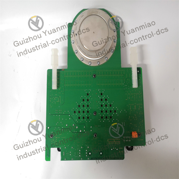
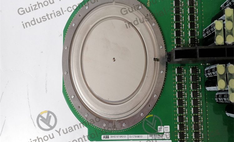
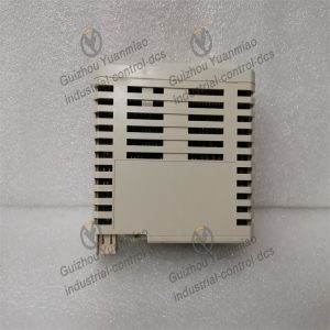
ABB 5SHY3545L0016 IGBT module
Structure and Packaging
By adopting advanced packaging technology, IGBT chips are integrated with related drive circuits, protection circuits, etc. in a compact module. This packaging form has excellent electrical insulation performance and mechanical stability, and can adapt to various harsh working environments.
The pin layout design of the module is reasonable, which is convenient for installation and connection to external circuits, and is conducive to improving the integration and reliability of the system.
Electrical parameters
Emitter voltage (Vce) : The rated voltage is typically 1700V, which enables this module to operate stably in medium and high voltage power electronic systems, withstand high voltage stress, and provide a guarantee for the safe operation of the system.
Collector current (Ic) : At a shell temperature of 25℃, the continuous collector current can reach 600A. When the shell temperature rises to 100℃, the continuous collector current is 450A. The peak collector current can reach 1200A, which can meet the driving requirements of high-power loads and has a strong load-carrying capacity.
Gate-emitter voltage (Vge) : The allowable voltage range is ±20V. Within this range, the IGBT can operate normally and has a good response characteristic to the gate drive signal, facilitating precise control of the on and off of the IGBT.
Switching characteristics
Turn-on time (ton) : The typical value is approximately 1.0μs. The time from the application of the turn-on signal to the full conduction of the IGBT is relatively short, which can quickly respond to the drive signal and achieve rapid connection of the load.
Cut-off time (toff) : Generally around 2.0μs, the cut-off speed is also relatively fast, which can quickly cut off the collector current, reducing energy loss and reverse recovery issues during the cut-off process.
Switching frequency: This module is suitable for operation at a relatively high switching frequency, generally reaching 20kHz – 50kHz, depending on factors such as application scenarios and heat dissipation conditions. A higher switching frequency helps reduce the size and weight of the filter in the system and increase the power density of the system.
Loss characteristic
On-state loss: In the conducting state, a certain power loss will occur due to the collector current passing through the IGBT. Its on-state resistance is relatively low. At the rated current, the on-state loss is usually between tens of watts and hundreds of watts, and the specific value is related to factors such as the collector current and the conduction voltage.
Switching loss: During the switching process, due to the charging and discharging of the junction capacitance of the IGBT and the changes in current and voltage, switching loss will occur. The higher the switching frequency is, the greater the switching loss will be. For 5SHY3545L0016, under typical switching frequency and load conditions, the switching loss is generally between tens of watts and hundreds of watts. By optimizing the drive circuit and heat dissipation design, the switching loss can be effectively reduced and the efficiency of the module can be improved.
Reviews
There are no reviews yet.