
Description
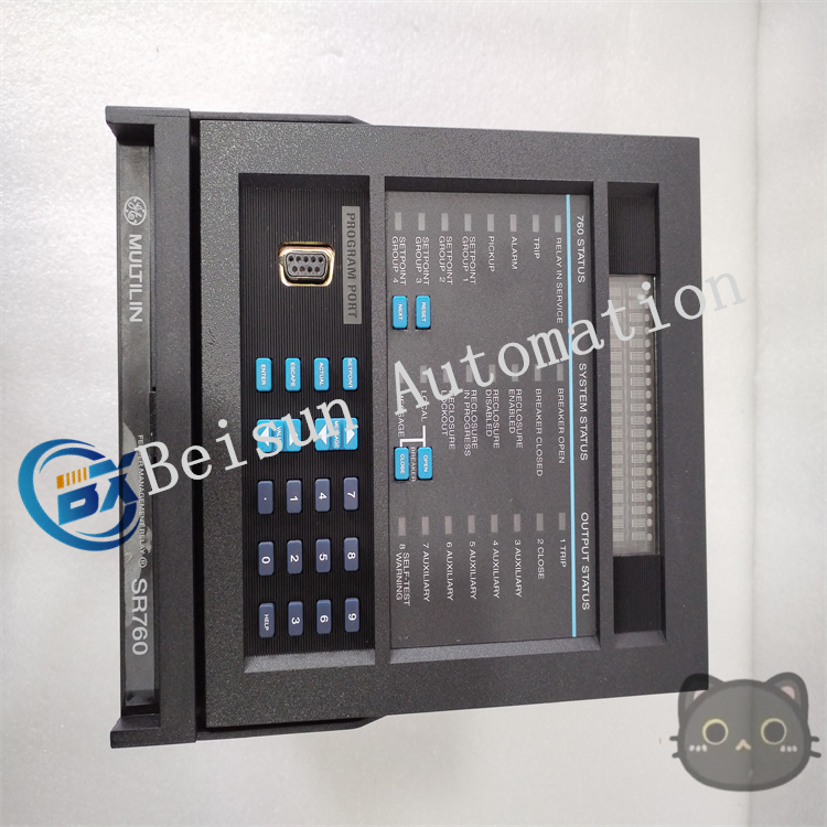
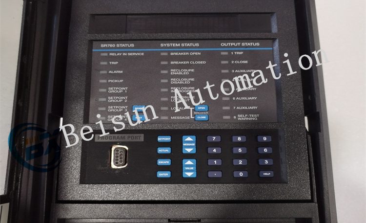
GE 760-P1-S1-LO-A20-G-T Feeder Protection Relay
The GE 760-P1-S1-LO-A20-G-T feeder protection relay is a microprocessor-based digital protection device. Its working principle is primarily based on real-time monitoring, analysis, and comparison of power system parameters, triggering corresponding protection actions through logical judgment. The detailed description of its core working principles is as follows:
1. Signal Acquisition and Preprocessing
Current/Voltage Transformer Interfaces
The relay collects three-phase current (IA, IB, IC) and voltage (VA, VB, VC) signals in the power system through built-in current transformer (CT) and voltage transformer (PT) interfaces. These signals typically originate from primary equipment of the power system (such as transformers and lines).
Signal Conditioning and Digitalization
Analog signals are filtered and amplified, then converted into digital signals via a high-precision ADC (analog-to-digital converter). The sampling frequency is usually 64 points per cycle or higher to ensure signal accuracy and dynamic response capability.
2. Digital Signal Processing and Algorithm Analysis
Fast Fourier Transform (FFT)
Converts time-domain sampling data into frequency-domain components, separating fundamental waves, harmonics, and DC components to extract amplitude, phase, and frequency information of current/voltage.
Protection Algorithms
- Overcurrent Protection: Calculates the root mean square (RMS) value of current, compares it with set thresholds (TOC/IOC), and triggers time-overcurrent or instantaneous protection.
- Ground Fault Protection: Monitors ground faults through zero-sequence current (3I0) or neutral voltage, supporting directional judgment.
- Voltage Protection: Monitors voltage amplitude, negative-sequence voltage (reflecting asymmetrical faults), and zero-sequence voltage (reflecting ground faults).
- Frequency Protection: Real-time calculation of system frequency to detect overfrequency/underfrequency conditions (e.g., 81O/81U functions).
3. Logical Judgment and Decision-Making
Comparators and Logic Gates
Compares processed electrical quantities with preset settings (such as current thresholds and time delays), forming protection criteria through combinations of logic gates (AND, OR, NOT).
Fault Type Identification
Differentiates between different fault types (such as three-phase, two-phase, single-phase ground short circuits, overloads, undervoltage, etc.) based on the variation characteristics of current and voltage (such as abrupt changes and phase relationships).
Action Logic
When protection conditions are met, it triggers the corresponding output relay to issue tripping commands or alarm signals.
4. Action Execution and Output
Relay Outputs
Built-in multi-channel programmable relay outputs (Trip, Alarm, Block, etc.), controlling circuit breakers, contactors, or other devices through contact closure/opening.
SOE Event Recording
Records the precise time (timestamp accuracy ≤1ms) and sequence of protection actions for fault analysis and responsibility tracing.
Waveform Capture
Records current/voltage waveforms before and after a fault (typically 2 cycles before the fault + 8 cycles after the fault) to facilitate analysis of the fault development process.
5. Communication and Data Interaction
Multi-Protocol Support
Through RS232/RS485/Ethernet ports, it supports protocols such as ModBus RTU/TCP and DNP3.0, communicating with SCADA systems, host computers, or other intelligent devices.
Real-time Data Transmission
Uploads measured values (current, voltage, power), device status, and event records to the monitoring system, supporting remote configuration and control.
6. Self-Diagnosis and Redundancy Design
Internal Self-Inspection
Monitors the operating status of the relay’s own hardware (CPU, memory, I/O interfaces) and software in real time, triggering alarms or blocking protection when abnormalities are detected.
Redundancy Design
Key circuits adopt redundant configurations (such as dual CPUs and dual power supplies) to improve reliability; supports hot-swappable module replacement to reduce maintenance downtime.
Typical Application Scenarios
- Feeder Protection: Monitors overcurrent, short circuits, and ground faults in distribution lines, quickly isolating fault sections.
- Busbar Protection: Serves as backup protection for busbars to prevent the spread of busbar faults.
- Distributed Generation Integration: Protects the interconnection interface between distributed generation systems and the power grid, supporting islanding detection and rapid disconnection.
Conclusion
The GE 760-P1-S1-LO-A20-G-T achieves fast and reliable protection actions by real-time collecting power system parameters and analyzing fault characteristics using digital algorithms. Its digital design provides higher precision, flexibility, and communication capabilities, adapting to the intelligent management needs of modern power systems. For detailed configuration guidelines, it is recommended to refer to the official technical manual of the GE Multilin 760 series.

Reviews
There are no reviews yet.