Description
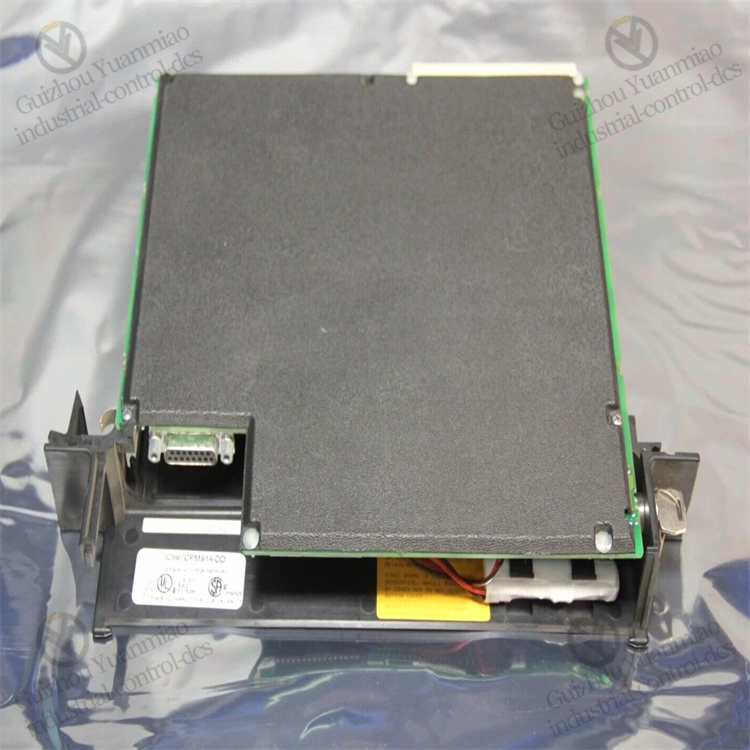
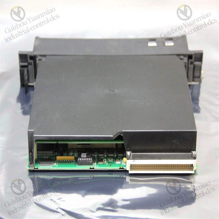
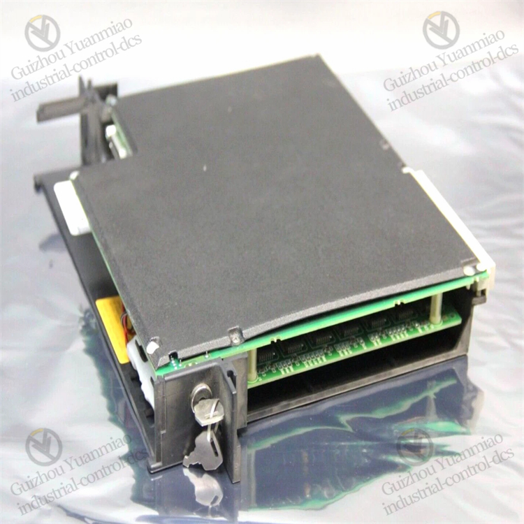
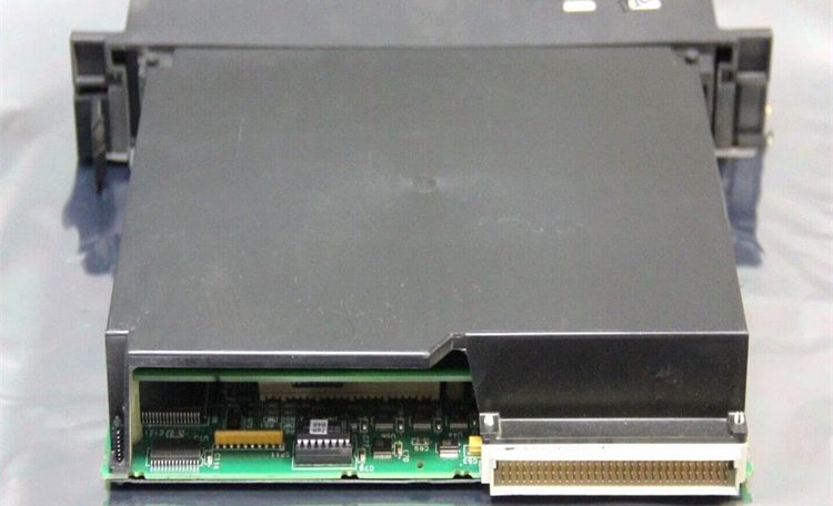
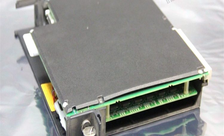
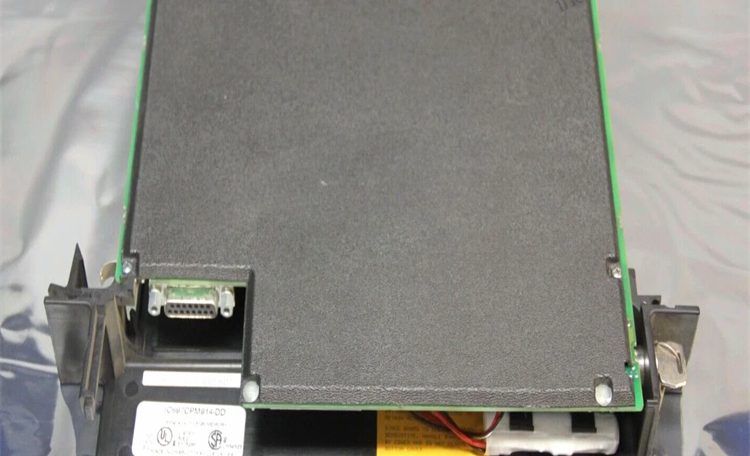
GE IC697CPM914 90-70 series GMR redundant CPU module
The IC697CPM914 is a GMR (Genius Modular Redundancy) redundant CPU module in the GE Fanuc Series 90-70 PLC, specifically designed for high-reliability industrial control scenarios. It ensures the system can continue operating even in the event of a single-point failure through its redundant architecture. Its working principle revolves around the core of “redundant fault tolerance,” achieving high availability by combining hardware design, data synchronization, and fault switching mechanisms. Here is a detailed analysis:
I. Core Design: Foundation of Redundant Architecture
The IC697CPM914 must be used in pairs (primary CPU + standby CPU) and paired with redundant power supplies, redundant racks, and GMR network components to form a complete redundant control system. The core goal of its hardware design is to eliminate single-point failures, which specifically includes:
- Dual CPU modules: The primary CPU and secondary CPU operate in parallel with completely consistent hardware specifications to ensure performance matching.
- Shared memory/synchronization links: Real-time data exchange between the two CPUs is achieved through a dedicated high-speed synchronization bus (such as GMR backplane or fiber optic links), with a synchronization cycle typically in the millisecond range.
- Redundant I/O interfaces: Supports connection with redundant I/O modules (such as the IC697I/O series) to ensure input and output signals are consistent between the primary and standby CPUs.
II. Working Mode: Primary-Standby Collaboration and Synchronization
The redundant system of the IC697CPM914 operates in a “primary control + hot standby” mode, with the specific process as follows:
1. Normal Operation Phase: Primary CPU Controls, Standby CPU Synchronizes
-
Responsibilities of the primary CPU:
- Executes user programs (ladder diagrams, structured text, etc.), processes I/O signals, and updates process data.
- Continuously sends real-time data (including program execution status, I/O data, internal register values, fault diagnosis information, etc.) to the standby CPU via the GMR synchronization bus.
- Monitors its own hardware status (such as temperature, memory, communication links) and the status of the standby CPU, and sends “heartbeat signals” regularly.
-
Responsibilities of the standby CPU:
- Receives synchronization data from the primary CPU, replicates the primary CPU’s working status in real-time (including program execution progress and data register values), but does not directly control external I/O.
- Independently monitors its own hardware and synchronization link status, and feeds back abnormalities to the primary CPU if detected.
- Maintains a “hot standby” state (initialization completed, ready to take over control at any time) with no switching delay.
2. Fault Detection and Switching Mechanism
When the system detects a fault (such as a primary CPU failure, synchronization link interruption, power failure, etc.), it automatically triggers the switching process to ensure uninterrupted control:
-
Fault detection methods:
- Hardware self-inspection: Both primary and standby CPUs regularly detect their core components (such as processors, memory, bus interfaces). If errors are found (such as checksum mismatch, timeout), they are marked as faulty.
- Heartbeat monitoring: The standby CPU continuously receives “heartbeat signals” from the primary CPU. If no signals are received for consecutive cycles (configurable, usually 2-5 cycles), it determines that the primary CPU has failed.
- Synchronization link monitoring: If the synchronization data transmission between the primary and standby CPUs is interrupted (such as fiber optic cable breakage), both parties confirm the link status through the redundant network to avoid misjudgment.
-
Switching process:
- Fault determination: After confirming that the primary CPU has failed or the synchronization link is unavailable, the standby CPU triggers a “takeover request.”
- Role switching: The standby CPU switches to “primary CPU” mode, immediately takes over control of the I/O modules, and continues executing the user program (based on the latest synchronized data).
- Fault alarm: The new primary CPU sends fault information (such as fault type, timestamp) to the SCADA/HMI system through a communication module (e.g., IC697CMM741) to alert maintenance personnel.
- Standby reconstruction: If the faulty primary CPU is repaired and reconnected to the system, it automatically switches to “standby CPU” mode, synchronizes data from the current primary CPU, and restores the redundant state.
III. Data Synchronization Technology: Ensuring Primary-Standby Consistency
Data synchronization between the primary and standby CPUs is the core of the redundant system. The IC697CPM914 adopts a combination of incremental synchronization and periodic full synchronization to balance real-time performance and reliability:
- Incremental synchronization: After each program execution, the primary CPU only sends changed data (such as updated registers, I/O status) to the standby CPU, reducing data transmission volume. The synchronization delay is usually < 1ms.
- Full synchronization: At regular intervals (configurable, e.g., 100ms), the primary CPU sends complete system status data (including program code, configuration parameters, historical fault records) to ensure the standby CPU is completely consistent with the primary CPU and avoid cumulative errors from incremental synchronization.
- Data verification: All synchronized data is accompanied by a check code (e.g., CRC32). The standby CPU verifies data integrity upon receipt. If verification fails, it requests retransmission to prevent synchronization failures caused by incorrect data.
IV. GMR Network Collaboration: Redundant Expansion Support
The IC697CPM914 must work with GE’s GMR network components (such as redundant switches, fiber optic modules) to achieve global redundancy. Its working principles include:
- Redundant communication links: Communication between the primary/standby CPUs and I/O modules, as well as upper-level computers, is transmitted through dual links to prevent a single network failure from affecting control.
- Global time synchronization: Through NTP or dedicated synchronization signals, the clocks of the primary/standby CPUs, redundant I/O, and remote sites are ensured to be consistent, avoiding timing conflicts in distributed control.
- Fault isolation: When a fault occurs in an I/O module or remote site, the GMR network isolates the fault point, and the primary CPU only processes the control logic of the normal area without affecting the overall system operation.
V. Application Scenarios: Why Redundant CPUs?
The working principle of the IC697CPM914 determines that it is suitable for critical industrial scenarios where downtime is not allowed, such as:
- Power industry (substations, generator set control): Downtime may cause large-scale power outages.
- Petrochemical industry (continuous production equipment): Fault-induced downtime may lead to safety accidents or huge economic losses.
- Rail transit (train signaling systems): Control interruptions may cause operational accidents.
Through its redundant design, the IC697CPM914 can increase the system’s Mean Time Between Failures (MTBF) to tens of thousands of hours, meeting high reliability requirements.
Summary
The working principle of the IC697CPM914 can be summarized as: “Dual CPU hot standby + real-time data synchronization + fast fault switching.” It eliminates single-point risks through hardware redundancy, ensures consistent primary-standby status through efficient synchronization, and achieves seamless switching through intelligent detection, ultimately providing “zero-downtime” level reliability guarantees for industrial control systems. Its core design is to maximize system availability without sacrificing control performance, making it a key component of the GE 90-70 series for critical control scenarios.

Reviews
There are no reviews yet.