Description
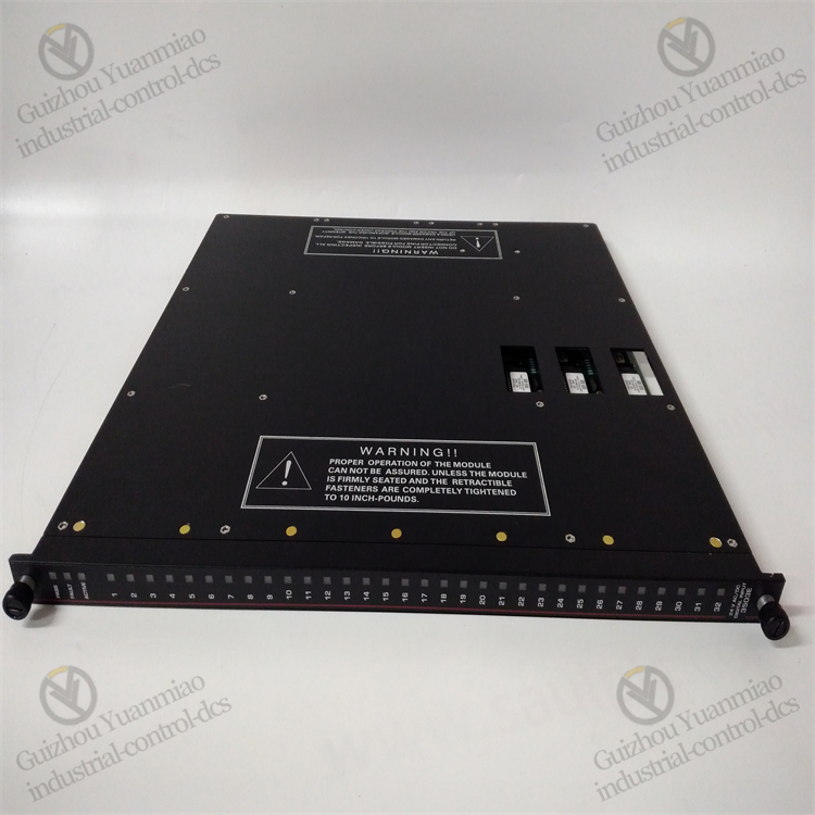
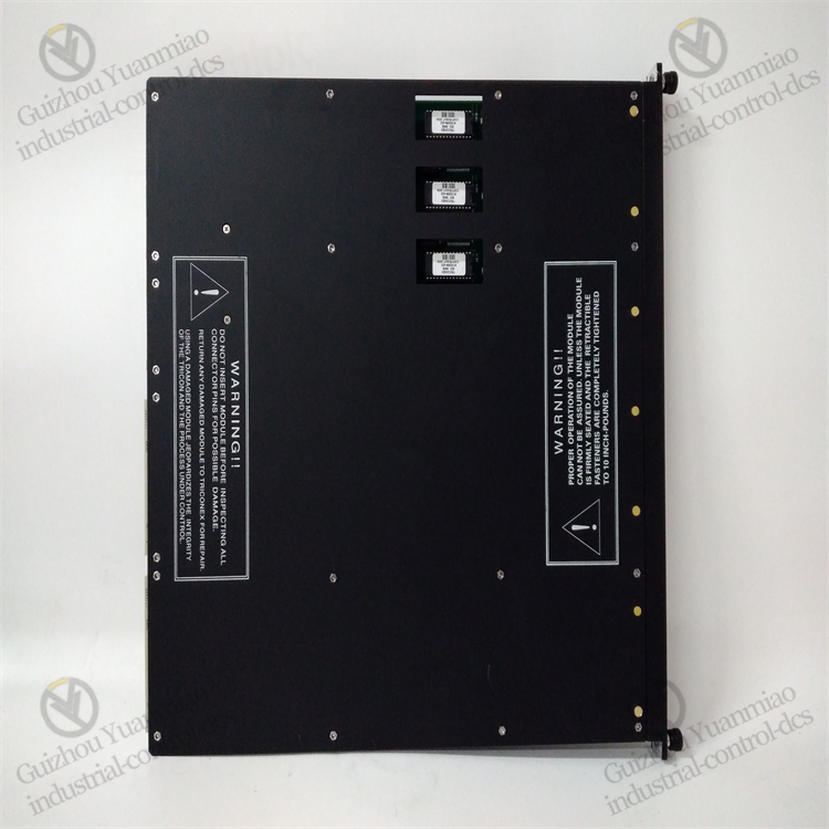
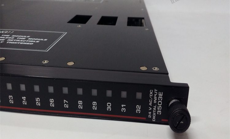
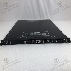
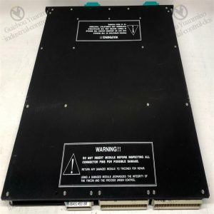
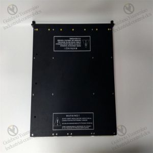
TRICONEX 3503E high-performance digital input module
Common Faults of modules and Their solutions
I. Hardware Connection and Signal Input Faults
1. No Signal or Abnormal Signal in Channels
- Fault Phenomenon: The displayed value of the module channel is 0, out of range, or fluctuates abnormally, inconsistent with the actual value of the field sensor.
- Possible Causes:
- Abnormal sensor power supply (e.g., 24V power failure) or loose/short-circuited wiring.
- Damaged signal transmission cable (e.g., open circuit in 4-20mA signal cable).
- Faulty sensor itself (e.g., failed pressure transmitter).
- Solutions:
- Use a multimeter to detect the sensor power supply voltage, confirm whether the cable connection is secure, and replace the damaged cable.
- Disconnect the sensor, connect a standard signal source (e.g., 20mA current) to test the module channel, and replace the sensor if normal.
2. Channel Accuracy Deviation Beyond Range
- Fault Phenomenon: The error between the collected value and the actual value exceeds 0.05% (module nominal accuracy).
- Possible Causes:
- Incorrect range configuration (e.g., module setting range does not match sensor output).
- The signal cable is too long or unshielded, subject to electromagnetic interference.
- Accuracy drift after long-term module operation (requires calibration).
- Solutions:
- Check the channel range configuration via TriStation software to ensure consistency with the sensor.
- Use shielded twisted-pair cables during wiring, keep away from power cables, and ground at a single point.
- Calibrate the module (requires professional tools and operation according to the manual).
II. Issues Related to Redundancy Architecture and Fault Voting
1. Triple Redundancy (TMR) Channel Voting Failure
- Fault Phenomenon: The module indicator light shows a channel fault (e.g., abnormal A/B/C channel indicator lights), and the system alarms “TMR Voting Error”.
- Possible Causes:
- Hardware failure in a channel (e.g., damaged ADC chip), leading to inconsistent signals in three channels.
- Strong on-site interference causes transient distortion of a single channel signal, triggering the voting mechanism.
- Solutions:
- View the diagnostic log via TriStation, locate the faulty channel (e.g., Channel A), and replace the module or contact the manufacturer for maintenance.
- If it is transient interference, check on-site anti-interference measures (e.g., adding surge protection or strengthening grounding).
2. Module Self-Diagnosis Alarm (Self-Diagnosis Fault)
- Fault Phenomenon: The “FAULT” light on the module panel is on, and the diagnosis shows internal hardware errors (e.g., power supply or communication link failure).
- Possible Causes:
- Abnormal module power input (voltage out of range) or damaged internal power module.
- Faulty communication bus (TriBus) interface chip or poor contact.
- Solutions:
- Detect the module power supply voltage (typically 24VDC±10%) and replace the faulty power module.
- Re-plug the module after powering off; if the alarm persists, replace the module and ensure the bus connector is free of oxidation.
III. Communication and Configuration Faults
1. Communication Interruption Between Module and Controller
- Fault Phenomenon: The controller cannot read module data, and TriStation displays “Communication Lost”.
- Possible Causes:
- Loose, damaged, or poorly connected redundant TriBus cable.
- Incorrect module address configuration (conflicting with other modules in the system).
- Wrong setting of communication protocol parameters (e.g., baud rate, parity).
- Solutions:
- Check the bus cable connection, replace the spare cable, and test the communication link resistance (should be close to 0Ω).
- Confirm the uniqueness of the module address via TriStation and reconfigure the address (e.g., DIP switch setting).
- Verify that communication parameters match the controller and restart the module to restore communication.
2. Configuration Parameters Cannot Be Saved or Take Effect
- Fault Phenomenon: After modifying the channel range or alarm threshold, the module does not operate according to the new configuration.
- Possible Causes:
- The “Download to Module” operation was not performed after modifying the configuration, or communication was interrupted during downloading.
- Module memory failure, unable to store configuration data.
- Solutions:
- Redownload the configuration in TriStation, ensuring no power failure or communication interference during downloading.
- If failure occurs frequently, try resetting the module (operate according to the manual); if invalid, replace the module.
IV. Environmental and Protection Faults
1. Module Overheating Alarm
- Fault Phenomenon: The module casing temperature is too high, the panel “TEMP” light is on, possibly accompanied by performance degradation.
- Possible Causes:
- Poor ventilation in the installation environment, and the temperature in the cabinet exceeds the module operating range (typically -40°C~70°C).
- The module cooling holes are blocked by dust, affecting heat dissipation.
- Solutions:
- Check the operation status of the cabinet air conditioner or fan, add cooling devices, and ensure the ambient temperature meets the standard.
- Clean the dust from the module cooling holes after powering off, and maintain the cabinet dust filter regularly.
2. False Alarms Due to Inadequate Anti-Interference Capability
- Fault Phenomenon: The module output fluctuates without on-site anomalies, triggering alarms (e.g., false jumps in flow signals).
- Possible Causes:
- Electrical isolation is not performed as required, and ground loops introduce interference.
- Strong electromagnetic sources (e.g., frequency converters, motors) on-site are not shielded.
- Solutions:
- Confirm the isolation voltage of each channel (≥500V) and use isolation transmitters to separate field signals from the module.
- Route signal cables individually through metal conduits, keep away from power cables (spacing ≥30cm), and ground both ends of the metal conduit.

V. Fault Handling Process and Maintenance Suggestions
Quick Location Steps:
- First check field sensors and cables (physical layer), then troubleshoot module configuration and communication (logical layer), and finally confirm hardware faults (e.g., replace spare parts).
- Use TriStation’s “Online Diagnosis” function to view the status of each module channel and error codes in real time (e.g., error code 0x10 indicates channel open circuit).
Preventive Maintenance:
- Regularly (quarterly) check the module indicator light status, heat dissipation, and terminal tightness.
- Calibrate the accuracy of key channels (using standard signal sources), record deviation trends, and replace aging modules in advance.
Safety Precautions:
- When replacing modules or wiring, disconnect the power supply first and confirm that the safety instrument system is in a safe state (e.g., ESD is bypassed).
- For scenarios involving SIL 3 certification, perform functional safety assessment again after fault handling to ensure compliance with standards.
Reviews
There are no reviews yet.